Pulse meters - part 2
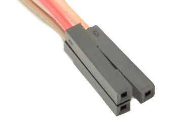
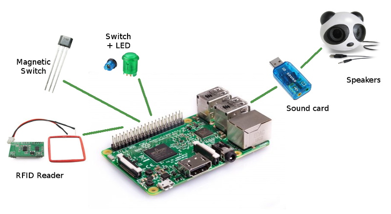
Here is my solution to connect the smart gas meter 'Gazpar'. This should also work for any pulse meter using a switch.
The idea is to keep the counter in RAM and thus the microcontroller always on.
Low power consumption
One of the challenges was to send the ATtiny85 to sleep and waking up only when either a pulse is counted or a serial character is received. I ended-up writing my own code but heavily influenced by this, this, this, this and this. It looks daunting at first but makes sense quickly.
The "PCINT0_vect" in the Interrupt Service Routine meaning all Interrupts from PCINT0 to PCINT5 is a catch and loads of people seem also confused by it.
Hardware Debouncing
The first attempt was using a capacitor to debounce the input. It worked flawlessly with the gas meter but these days debouncing tends to be done by the microcontroller itself.
In this case, the counting (increment) is done in the interrupt function itself (The "PCINT0_vect" mentionned above).
Software Debouncing
This is were troubles started. Because it is not possible to use timers/delays in the interrupt function, the debouncing has to be done in the main loop.
After several iterations, mixing flags and jobs done half synchronally, half asynchronally, the final (working) solution is also the simplest.
Loop
In the end, the loop is fairly straightforward and could be summarised by:
- Go to sleep.
- If woken-up by a serial change, stay awake for 5s before going to sleep. If command received by serial port, read the command and send the reply.
- If woken-up by a signal change, stay awake for 0.5s before going to sleep. Read current status of pin 7 (PB2). On a falling edge, increment the counter and publish the new value over the serial port. Wait for 100ms before going back to the loop. This prevents transitions faster than 200ms.
Development
The development was done on the Arduino IDE using https://github.com/SpenceKonde/ATtinyCore using an Arduino Uno as the programmer.
Backup during power outages
Goldcap/Supercap/EDLC
The firt idea was to use a supercapacitor (something like 1.5F 5.5V) with a schottky diode in order to maintain the MCU powered.
In theory, it's easy to implement and should work like a treat (between for example 5V and 1.8V). In practice, there were some issues with the "initial" charging (big drop of voltage) and I was disappointed by the performances. Moreover, there is the issue of a big variation of voltage of the supercap (can drop under 2V) in relation to other pins (Vcc, serial).
I am pretty sure that there are good ways to deal with these matters but they certainly require more investigation. It could also explain why, even nowdays, RTC on motherboards are still mainly powered by battery cells rather than supercaps.
Battery
An alternative was to use a simple CR2032 lithium battery. These StackExchange answers were a good way to start. This AN1535 application note, also gives a complement (cf Figure 3).
This last document is were I was made aware that the reverse leakage current could be a big issue. I have no plans to have any of my circuits "UL approved" and don't have to follow any american requirements but at the same time, if a risk exists with batteries on the other side of the pond, it is the same over here.
I was planning to use BAT48 Schottky diodes but they may have a higher leakage current than the recommended value (1µA). Renasas Application Note mentions BAT54. The bad new is they exist only as SMD (SOT23-3). The good news is there is a "C" variant which incorporate 2 diodes.
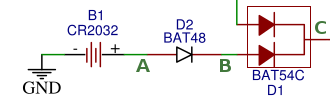
In the end, I put a BAT48 + BAT54C.
Vcc and serial communication were also switched to 3.3V in order to keep all voltages as close as possible.
When running on battery, the following values were measured with a fresh cell:
- Voltage of battery : 3.12V (A)
- Voltage between GND and after BAT48 and BAT54 diodes (B) : 2.98V
- Voltage between GND and Vcc PIN of ATtiny (C) : 2.87V
Which gives the following drops:
- BAT48 = 0.14V
- BAT54 = 0.11V
Note that drops are higher (~ .2V) when measured using a multimeter in diode mode. Possibly because the current is higher.
First foray into SMDs
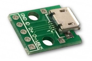
As mentionned above, BAT54C diodes only exist in SOT23-3 format. Since even through-hole component can be challenging (specially with bad solder, but this is another issue), I have never been too keen in the SMD variants of components. That said, I discovered that this is a vast world with loads of different sizes (from doable to sheer madness).
Since I hadn't received my SOT23-3 to SIP-3 adapter boards, I decided to solder it directly on the 2.54mm pitch prototype board! Ugly but it worked fine on the first attempt so...
SMDs (at least the 1206 size) might not be evil after all!
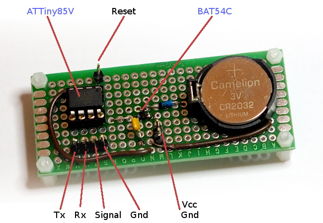
Pins and ISP
Since PB0, PB1 and PB2 were available without anything else connected to them, I realised that I basically had almost everything ready for "In-system programming". So I added a "reset" pin (PB5). Et voilà.
| Pin on board | Pin on chip | Main function | ISP function |
|---|---|---|---|
| Tx | 5 (PB0) | Serial (Tx) | MOSI (Arduino 11) |
| Rx | 6 (PB1) | Serial (Rx) | MISO (Arduino 12) |
| Signal | 7 (PB2) | Counting (switch) | SCK (Arduino 13) |
| Gnd | 4 | Counting (switch) | Gnd |
| Gnd | 4 | Power | |
| Vcc | 8 | Power | 5V |
| Reset | 1 (PB5) | NC | Reset (Arduino 10) |
Disclaimer
As usual, this page is for informational purposes only... You assume total responsibility and use at your own risk!
Next time, I'll describe the installation in situ and the (very simple) communication protocol.