While shopping for a Zigbee receiver (more about it another time), I spotted a fridge sensor Telldus (312716) looking exactly like my F007TH sensors but with a cable and measuring temperature only.
Protocol?
Honestly, the information gathered on different sources about these was totally unclear but I decided to buy one for my chest freezer.
And... obviously, the casing is identical BUT the protocol (F007TP here) is absolutely not compatible with the F007TH. To be clear: they have nothing in common!
Yet, this new sensor was recognised by my RTL-SDR adapter running rtl_433 (but with the wrong temperature -- according to the source code there may be a conflit bitween WH2 & WH5 which are part of the same family).
Decoding
It appears that the protocol was described more than 10 years ago by Luc Small on his blog, so at least the heavy lifting was done. I only had to use the decoding and CRC calculation in my own code.
Hosting
As I didn't want to requisition a specific ESP8266 just for one sensor and because it was in the same area as the rain gauge, I decided to merge the decoding functions even if there is very little in common between these 2 applications.
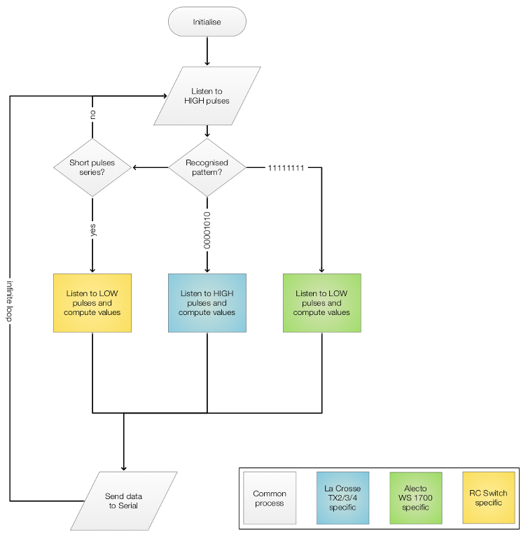
It is unfortunate that the WH2/F007TP protocol doesn't have an easy synchronisation preamble but at least the rain gauge do, so the main loop now checks if there are a number of ~500ns pulses followed by one ~1500ns or if it detects one ~7500ns pulse.
If it's the latter, then it records 64 pulses then calls the rain gauge decoder.
If it's the former, then it records 40 pulses then calls the F007TP decoder.
Overall, the routing mechanism is similar to the solution used for 433Mhz remote sockets.
Code
The code is available online (Plateform.IO format this time).
Having bought a Wireless Rain Gauge from Pearl Diffusion, and since they looked alike, I was hoping that even if the model number was different, its protocol would be similar to the TFA DROP 47.3005 which is implemented/documented by rtl_433.
It turns out that they are similarities (they might come from the same factory) and also quite a few differences.
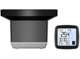
For reference, here is the inFactory FWS-275 (aka NX-6331-675):
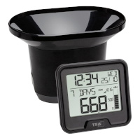
And here the TFA 47.3005 (aka TFA 30.3233.01):
Looking for the data
Signal
I decoded several protocols in the past, mainly using dumps of timing on Arduino serial port. Here, the author of the TFA device's code (helped by one of the maintainers of rtl_433) gives a few clues in how to proceed rapidly in the issue associated.
rtl_433 -A
manages to collect the format of the signal and a way to display some formated information:
The signal seems to be composed of 2700µS and 970µS pulses with 7340µS synchronisation pulses. One suprising thing is that it doesn't seem to be regular (for example long HIGH + short LOW or the opposite). It is a mix of long HIGH + short/long LOW or short HIGH + short/long LOW). But it we take into account only the HIGH side, it doesn't matter much.
Data
When decoded (PWM slicer), the first chunk is always different (values divided by 2), probably due to a shifted bit. The second and the third are almost identical, except the last byte. Best is to ignore it and see.
bitbench is another handy tool to carry on with the decoding.
Protocol
One (obvious) difference between the two gauges mentionned above is that the one I own also a outdoors temperature display, so the protocol has to transmit the value.
The 2 first bytes never change except after a change of batteries on the outdoor unit, so it is certainly a random ID.
The third byte follows the pattern 00, 02, 04, 06, 08, 0a, 0c, 0e already found in the TFA unit. Like on the TFA, bit 7 is the battery indicator (tested using a variable power supply to lower the voltage) and bit 6 a reset indicator.
The fourth and fifth bytes seem to be the counter of the bucket tips, using the same weird initial value (-10). More about it later
The sixth and seventh values are the temperature. Since, they didn't really match the Celcius display, I switched the display to Farenheit and in this case a change of value is also a change of display. This mean the transmission is in Farenheit (like in the F007TH protocol) but the encoding is diffent. After toying a bit, it appeared that the format is 16 bits Little Endian and that the value is in tenth of degrees Farenheit with an offset of 900.
Last but not least, the checksum... I was expecting something like on the TFA unit (it took me a while to understand zuckschwerdt's answers to be honnest) but after trying the referenced tools it turns out that the checksum is just that... a sum of the first 7 bytes!
All was fine... except that the main reason of this apparatus is to mesure the amount of rain, and there was not an obvious link between the counter values and the display!
Knowing that the base is 25.4mm (top of the tube on the display), it is almost certain that the mesurement is with imperial units too.
After tiping the bucket (by hand) a few hundred times, it seems that the value is 1 tip = 0.0425 in of rain. Converted in metric, this gives 1 tip = 0.108 mm.
How on earth did they managed to select this kind of value??? Well never mind...
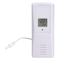
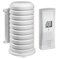
In order to complete and replace the old TX2/TX3 sensors, I found some new ones using a similar technology (still RF 433 Mhz). These are the TFA ref 30.3208.02 and can be bought with a very handy external housing (ref 98.1114.02):
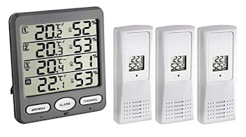
They also come in sets of 3 sensors + a "climate monitor".
(Edit 27/07/2022: PEARL Diffusion's rebranded NX-6185-675 sensors (sold for Infactory FWS-1000 station) are fully compatible too).
Technical info
The sensors themselves measure and display the temperature as well as the relative humidity. Up to 8 sensors can be used at the same time and their address is set (thus fixed) using microswitches, which is a huge improvement over the previous models (either IDs changing at reboot or limited to 3).
The communication protocol seems to be known as F007TH (from Ambient Weather) and presents 2 singular characteristics:
Various implementations exists and can be found on the Internet; last but not least my version, adaption of one of the different sources and for which I use on a ESP8266 as a gateway to the MQTT broker.
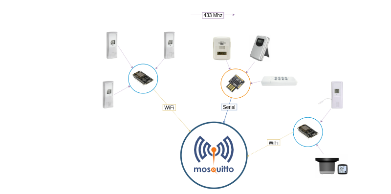
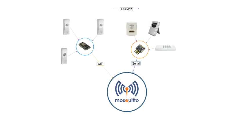
My current ecosystem as a diagram
So far the described ecosystem can be represented as:
As mentioned previously, the kit I bought has 2 sockets. But knowing that the remote can control 4 (it has a total of 8 buttons), it would be good to be able to use the remaining unused buttons. And why not, since the state of the socket can't be retrieved, to intercept and store the current state.
Maybe there is a way to squeeze yet another protocol?
It turned out that it was quite easy to do without much interference to the existing two decoding pipelines!
Meet the 433Mhz receiver
Basically, the signal from the remote will appear as a series of High pulses which are shorter (~ 320µS & ~ 960µS) compared to the one from the sensors (~ 500µS/1300µS and 1900µS/3800µS). If a string of these specific pulses is detected, then we switch to the remote decoder.
The signal being sent at least 3 times from the remote, this mean that we can intercept the second or the third transmission. The transmission itself starts with a "very long" pulse (31 times the base pulse). The encoding is based on a tri-state system which basically means, since we can ignore the floating state, that every other bit must always be a 1. The data consists in the address part, the button part and the state (ON/OFF) repeated but inversed.
For example:
101011101011101010101110
can be decoded in (checking then removing all the odd bits):
001001000010
and interpreted as:
address (DIP switches): off-off-on-off-off
button: A
Action: On
Code
Since there is now a little bit more than Lacrosse sensor decoding, I renamed the project on GitHub to 433Mhz receiver...
Since I embraced the MQTT protocol, I added the conversion and now any touch on the remote control is translated into something like (to carry on with the example above):
Topic: cm/remote-00100/action/a
Payload: {"ts": 1451215192, "value": "on"}
The first part is complete. Hooking up a 433 Mhz emitter (remember this?) on the Raspberry Pi is easy but for both technical and whimsical reasons, I have something else in mind...