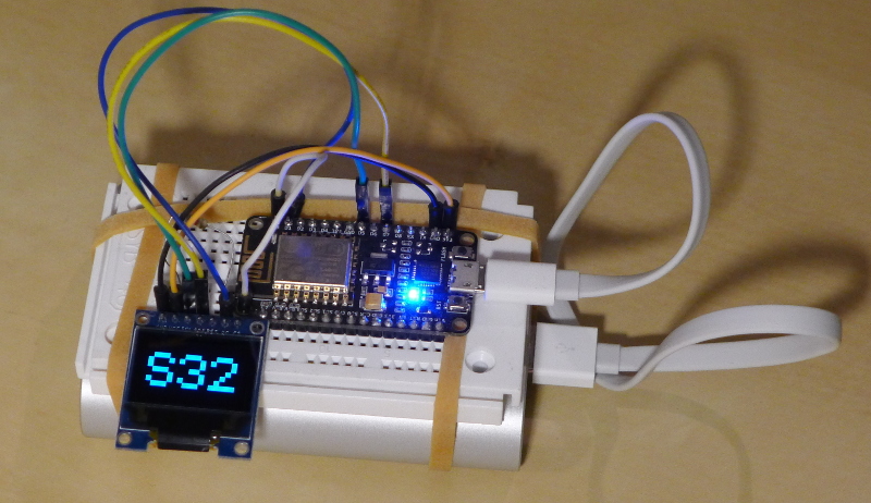
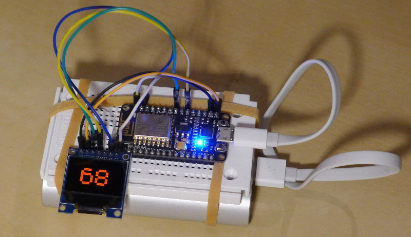
Tick, tock, tick, tock... When time is up, lie-ins and good nights become a thing of the past!
Counter using a ESP8266 (nodemcu) and OLED Colour display and accessing NTP. The code can be found at the following address: https://github.com/guillier/Time_Bomb.
This time, it is about playing with a ESP-201 as well as with the Nodemcu devkit but without nodemcu (the firmware). Here are a few notes about what I discovered while playing with these boards.
Arduino
As I mentioned in the past, starting with Arduino 1.6.4, there is now full support for ESP8266.
Libraries
A majority of the Arduino's functions are directly available to be used of the ESP8266 and some additional libraries have been directly developed specifically. The libraries and documentation are changing extremely fast: between my first attempts in the summer and now, a lot of material was added.
Programming
The biggest hurdle with these chips seems that timing. While a "normal" Arduino will happily wait for any kind of event to happen, the ESP8266 tends to reset very easily. Too easily maybe and I wasn't able to do some tasks such as the La Crosse decoder and its strict timings.
There is more info about watchdog in the documentation and in this interesting blog entry about porting code from the Spark Core to the ESP8266.
WIFI
This is the whole point of these modules! If connecting is easy (at least in theory!), keeping the connection alive is a bit more of a challenge. Keeping a eye on the status is essential.
Nodemcu
The nodemcu devkit already mentioned here has 2 switchs: "RST" and "FLASH".
But in practice, they are not used thanks to a clever system (See "USB TO UART" on the schematics)... Flashing mode and reset are done automatically!
Debug with GPIO2
Boot
The second Serial output is something nice and not widely documented with ESP8266 modules: GPIO2 (aka pin D4) can indeed be used for debug purpose.
For example on one of my modules, if I press reset, I obtain the following message:
Moreover, it is also possible to write from the programme to this serial port and it is very easy. As the Arduino documentation put it:
To use Serial1, call Serial1.begin(baudrate).
But you have to remember that you can only write (only TX exists).
Connection
Simply connect GPIO2/D4 and GND to a serial adapter. Speed settings should be 115200 8N1 but as usual with these modules, your mileage may vary.
Different models of Nodemcu
There are quite a few versions of breakout board, all more or less compatible. Below a selection of the most famous ones (I am not even including the clones):
In previous posts, I mentioned a problem with ESP8266 modules when using a Orange Livebox (the router let by my ISP). It was confirmed by someone else (thanks you Sébastien H.) that splitting into 2 SSIDs 2.4 Ghz & 5 Ghz and forcing all clients on the 2.4 Ghz helps.
I also received a few queries about how I worked around this problem...
Well, basically, I bought a Wifi dongle I installed on my Raspberry and created a new totally private network aside. It probably helps a tiny bit with security but it is a bit of a pain with kernels/modules as my dongle is not recognised with the standard kernel.
An alternative could have been to use a cheap Wifi repeater/booster since most of them just create a new SSID bridged to the base network. The risk being this new bridge behaving like the Livebox.
As indicated above, I have an issue with the default kernel module 8188eu... The Wifi dongle is only half recognised and doesn't initialise properly. Fortunately, a functional version can be found pre-compiled here: https://www.raspberrypi.org/forums/viewtopic.php?f=28&t=62371.
First, find the filename name in the list according to the dongle and the kernel version
uname -a
Then the module can be downloaded for Raspberry P1 or P2 (look for dl.dropboxusercontent.com/u/80256631/8188eu-2015yyzz.tar.gz or dl.dropboxusercontent.com/u/80256631/8188eu-v7-2015yyzz.tar.gz on the page).
Once installed, all Wifi tools (and in particular iw ) should work properly.
A few months ago, I noticed a very strange behaviour of the ESP8266 modules with my main router.
And as a workaround, I used a second Router/Access Point while carrying on tests with more recent firmwares. So far no luck. Since the problem is present with AT, LUA & "Arduino" versions, I assume the bug is more on the SDK side.
Even the latest AT firmware based on the Espressif SDK — 1.4.0 at the time of writing — still exhibits the bug dispite the hopes given with a changelog such as "WiFi compatibility problem of special network card"!
A few people reported the problem as well, all using a Orange Livebox as the router. This message describes exactly what I noticed and I agree with the explanation.
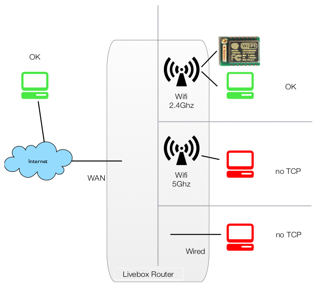
Basically, on the LAN side, the Livebox is composed of 3 interfaces, all bridged together:
A 4-port wired Gigabit switch
A 2.4Ghz Wifi (with its own SSID)
A 5Ghz Wifi (with its own SSID)
And on the other side of the router, a WAN port.
The ESP8266 modules (using the 2.4Ghz) seem to work with the following conditions:
ESP & anything outside the local network => TCP/UDP OK
ESP & other 2.4Ghz device: Bi-directional ==> TCP/UDP OK
ESP & 5Ghz device: UDP from ESP to device ==> OK, Others (espcially TCP) KO
ESP & wired device: Same as above: Only UDP in one direction
This sounds a bit like a joke... the module can talk (or can be accessed if port-forwarding is set-up) to anything in the world... but not to a local server!!!
TBC...
EDIT (04/09/2016):
I was recently contacted by someone called Chris who, while trying OTA on ESP8266 found out that newer versions of the "Arduino boards" (aka firmwares) seem to solve the problem.
I tried on my side and indeed, the problem seems to disappear with version >=2.0.0 (current is 2.3.0)... (click update on the "Boards Manager"). Glad to see this bug gone. Thanks Chris for this great news.