Following the upgrade of my electricity meter (from rotating disk to latest generation of smart meter), I am now able to use the Teleinformation output (hurrah!)
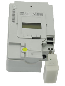
Linky
The Linky smart meter has a slot for a "LRT" module and a 3-pin header for teleinfo (the traditionals "I1" & "I2" as well as a power source named "A").
There are also two communication modes available: Historical (the only one available so far) & Standard (i.e. the new one starting with Linky).
LRT
The "Linky Radio Transmitter" (Emetteur Radio Linky) is a module developed to transmit the value to a household display. Specifications show they can be using either Zigbee or KNX. It was supposed to be totally open but I am yet to see a schematics of it.
At least the Interface Specification is available. I reused the name of Zigbee attributes for the MQTT publication.
Teleinfo
Official docs are available (in french) on Enedis's website, in particular NOI-CPT_02E for Teleinfo in general and NOI-CPT_54E for Linky in particular.
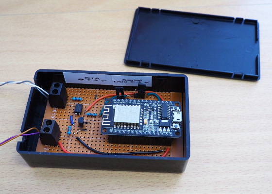
My board is vague cousin of Charles Hallard's Wifinfo but where most of the components are already embedded on the nodemcu module.
CH340G (USB to UART)
Something worth noting is that CH340G seems to be struggling with 7N1 (7 bits instead of the usual 8). Although it doesn't matter for day to day usage of the ESP8266, it makes tests (emulation of the Teleinfo frames) more difficult.
It could be the driver though I am using Linux. Using boards (Amica) based on CP2102 or FT232 didn't show any problem.
Power
From the meter
In theory, the pins "A" and "I1" are maint to be used as the power source. That said, the characteristics are 6 Vrms (50 kHz) and 130mW. This is far from the ESP8266 requirements (~ 150mA) and if it would be easy to rectify and smooth the current, a storage system (super cap or battery) would be needed to deliver peaks of currents every time the data is published (re-charging being one while module is in deepsleep).
External 5V source
To keep things simple and since I already had a 5V source at my disposal, I used the embeded regulator on the nodemcu board (through the Vcc pin but it could have been through the micro-USB socket).
OTA
Having the circuit permanently plugged to the meter means that the option of remote updates is a big bonus. The module is off/asleep most of the time so the best method was the HTTP Server one. But in order to make things easier and more secure, there is a physical jumper to allow OTA or not. When jumper is on open position, no OTA is possible. In the other position (closed), every time the program starts (i.e. every minute), it checks if an upgrade is available.
This is were the additional python script comes handy. By running a webserver and comparing the MD5 checksum of the firmware on the module to the one on the server, it is possible to launch the upgrade sequence only when necessary.
MQTT
Selected data is transferred using the MQTT protocol. As mentioned above, the names/topics used are based of the ones in the ERL/LRT documentation.
Since the tariff is a constant one and not a differential one, there is only one reading to report and there is no need to advertise which tariff is active. People dealing with Heures Pleines / Heures Creuses would have to change the code.
Deep sleep
In order to reduce the amount of power drained, reduce the heat production and because there was no need to keep the module on for nothing, I decided to turn the wifi off. But it turned out that it isn't as straightforward as it initially sounded. Just calling the corresponding fonctions doesn't really make any difference in term of power consumption and forums are full of examples looking really like black art.
On second thought, I decided to go to the deep sleep route which turned out to be easier to implement and perfectly adapted to this kind of usage. The teleinfo is continuous with values coming all the time but having a refresh every second or so has very limited interest. Even everything minute is kind of luxury.
The only downsides of deep sleep are the need of a physical wiring for reset purpose and that the programme really resets every time. In this case where the bridging is stateless (state/info is held by the smart meter and given every single time) it doesn't matter the least.
Next version
This version has been running for a while without any issue. Once the meter is properly registered by the supplier (they seem to have technical issues actually), they should be able to change the mode to "Standard".
This new mode is only in Linkys, uses a different serial speed (9600N7 instead of 1200N7) and provides more information. The "codes" are slightly different too.
There is no physical modification needed and everything is documented so making the software changes should not be too complicated.
Will see....
Code
As usual the code and schematics are available (AS IS) on github.
This project is a mashup of different experimentations. I wanted to try the SHT21 sensors and I was looking for a CO2 sensor at the same time accurate and not too expensive.
CO2 Sensor
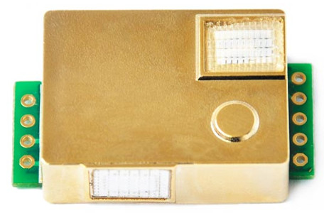
Until recently, gaz sensors were either analogue (and totally uncalibrated) or relatively expensive (when not both at the same time). Then came the MH-Z14 which is a affordable "Non-Dispersive InfraRed" sensor, in theory quite selective.
The MH-Z19 from the same company can be found for ~ $25. The main issue is the partial documentation. Some commands are still a bit obscure.
A great source of information is the wiki https://revspace.nl/MHZ19 and there a quite a few examples on github to get started.
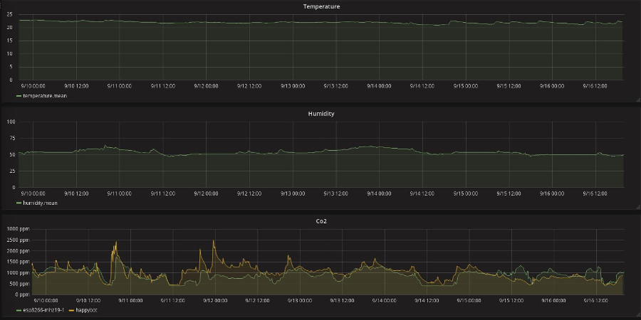
At first experimentations were a bit frustrating but after a while things started to stabilise a bit and sensor's readings from the past few month seem to make sense. The solution was to reject sub-standard readings and to average valid ones over a period of 5 minutes.
One quite annoying thing a bit this module when using breadboard or prototype PCB is that it has weird dimensions (not a multiple of 2.54mm) and won't fit nicely.
Calibration
Calibration can also be an issue, specially because of the ABC calibration every 24h. The system would be great if it spanned over let's say a week which would give you several chances to open the window but as it is (i.e. using the minimum value of previous day as base), reading were becoming strange day after day. It turns out that it works a lot better without ABC and a manual calibration from time to time.
Then manual calibration can be triggered by software or using the hardware pin. To avoid trying to fit a switch on the enclosure, the solution retained was to use a reed switch inside and to press a neodymium magnet on the cover once the air of the room has been well recycled.
Wemos D1 mini
Although I initially planned to use nodemcu modules, I decided to try Wemos D1 mini which are smaller, cheaper and able to cope with higher speed communication via USB so firmware upload is twice as fast.
Besides this, there really behave like any other ESP8266 solution. Wemos offers a good selection of shields (power, relay, LED, sensor, ...) which I haven't tried as well as modules based on the more powerful ESP32.
It is probably best to use their official online shop as there seems to be quite a lot of fake modules around, and not necessarily cheaper.
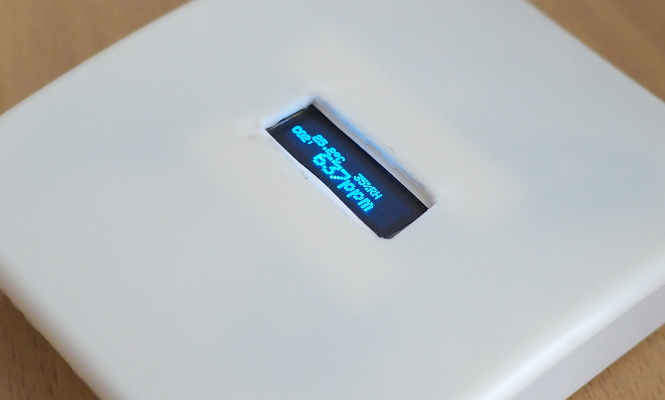
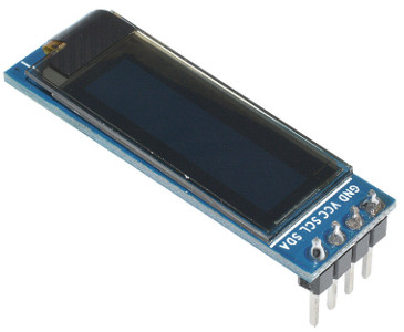
I2C Oled
Having used a 0.96" Oled screen for the time bomb, I really thought that using a 0.91" 128x32 I2C SSD1306 screen would be trivial. As it turns out, library for the former is not compatible with the latter because they lack of a proper framebuffer. After digging around, I found that the Adafruit library was working (one parameter is of a different value) even if the hardware looks quite different (more pins).
To be perfectly honest, if I was to make another sensor, I would give up the screen and use coloured Led shinning through (the plastic is slightly translucent) as the physical fitting was probably the most challenging part of this project (even if simple by DIY standard).
A sprinkle of MQTT
Communication with base is, of course, via MQTT, nothing new or complicated here. There is a sampling every minute for the CO2. The average value as well as the current values of temperature and relative humidity are sent every 5 minutes.
Wifi off (really?)
Since this new sensor is installed in our bedroom, I wanted to switch the Wifi on only when needed MQTT communication to send the values. I basically used the dedicated function for this. Is is really switching off "radiations"? Who knows... as I discovered with the electricity meter project, electric consumption is not lowered by it.
Powering the sensor
I knew from the start that using battery would be a challenge and I didn't even bother. Between the screen, MH-Z19 and the Wifi, it is probably around 200mA anyway. The USB port of the Wemos D1 mini is plugged directly on a small power adapter. The usb cable can also be used to upgrade the firmware as no OTA was implemented on this project.
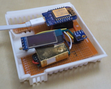
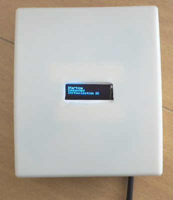
All in a "sensor box"
Like almost everything else, directly from China, I found an enclosure designed for sensors (or thermostat?) which was the right size to fit everything. The USB power adapter is external, the ESP8266 at the top and the thermometer at the bottom, by the vents in order to stay as accurate as possible. Despite this, the temperature appears 1.5°C higher than without cover. The offset can be corrected in software.
Code
As usual the code and schematics are available (AS IS) on github.
It includes a SHT library and MH-Z19 library.
Last summer, I hinted that I was about to switch from the monolithic programme with all its threads to a constellation of separate processes.
The main reason was that the monolithic application needs a restart for any change in the configuration and that a crash/exception on one thread breaks everything.
True, having several separate processes impose to find a way to start them all in the first place and something else to look after them. It also uses quite a bit of memory (because of Python overhead, a tiny process is almost as memory hungry as a small one). Last but not least, the interprocess communication can be problematic.
Enters the Raspberry Pi 2
Fortunately, the Raspberry Pi Foundation released the Raspberry Pi 2 which has now a quad-core CPU, 1GB of memory (and even the Raspberry Pi 3, more recently, but I doubt it would make much difference here). At ~ 3MB of memory per process, there is plenty of available RAM! And also, starting a Python process is now almost immediate compared to the 5-10 seconds needed on the 1-B+ model.
Communication : MQTT
Thinking about it, there is not much need of communication between processes. In the majority of cases, it is all bout sending the data to the display interfaces and to a database (for the sensor part).
Note that so far, I have very little automation (besides a couple of sockets).
Anyway, the ubiquitous MQTT can solve all the communication problems... These days, it seems that there isn't a similar hub project around which isn't using MQTT either at the core or at least for plug-ins communication.
I have already detailed the way I format the topic and the payload of the messages.
Every process is now using a bootstrap library which manages the daemonisation, the MQTT communication, and logs. There are 2 types of messages : the data and metadata (starting, heartbeat, ...).
Current state
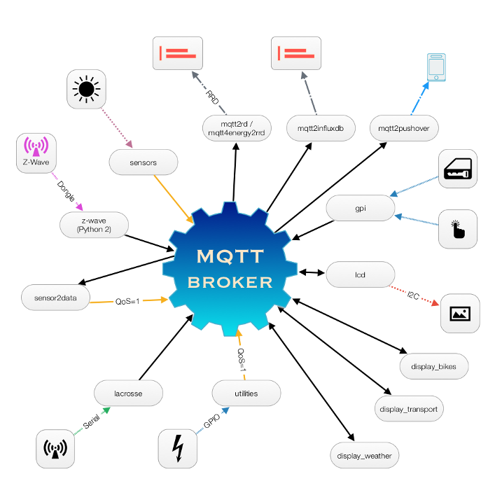
Currently the model used is the following:
Notes :
All measurements have the MQTT retain option activated to keep the last value available to a reconnecting process
Pushover is a notification system for mobiles (and desktop)
I am currently using 2 storage systems: RRD and a timeseries database (test in progress)
'display_bikes' and 'display_transport' call external webservices and/or doing web scraping of pages. Resulting data is only displayed but never stored.
MQTT used to be the acronym of MQ Telemetry Transport but is now just MQTT is now a OASIS standard for Machine2Machine data sharing. This protocol was invented by Andy Stanford-Clark (IBM) and Arlen Nipper (Arcom, now Cirrus Link) in 1999 and was designed for connections with remote locations where a small code footprint is required or the network bandwidth is limited.
Tutorials
The best explanations I found on the subject come from a series of blog posts by HiveMQ (even if I don't use their product):
There are other posts about security and clients but I think that the ten ones referenced above are a very good introduction.
Basic concepts of MQTT
There is also a IBM redbook called Building Smarter Planet Solutions with MQTT... which is a little bit old and geared towards IBM Websphere MQ product but still interesting and another good presentation of this protocol. Moreover it is free and available in numerous formats.
Extract from the book (chapter 1.2.3):
The MQTT protocol is built upon several basic concepts, all aimed at assuring message delivery while keeping the messages themselves as lightweight as possible.
Publish/subscribe
The MQTT protocol is based on the principle of publishing messages and subscribing to topics, which is typically referred to as a publish/subscribe model. Clients can subscribe to topics that pertain to them and thereby receive whatever messages are published to those topics. Alternatively, clients can publish messages to topics, thus making them available to all subscribers to those topics.
Topics and subscriptions
Messages in MQTT are published to topics, which can be thought of as subject areas. Clients, in turn, sign up to receive particular messages by subscribing to a topic. Subscriptions can be explicit, which limits the messages that are received to the specific topic at hand or can use wildcard designators, such as a number sign (#) to receive messages for a variety of related topics.
Quality of service levels
MQTT defines three quality of service (QoS) levels for message delivery, with each level designating a higher level of effort by the server to ensure that the message gets delivered. Higher QoS levels ensure more reliable message delivery but might consume more network bandwidth or subject the message to delays due to issues such as latency.
Retained messages
With MQTT, the server keeps the message even after sending it to all current subscribers. If a new subscription is submitted for the same topic, any retained messages are then sent to the new subscribing client.
Clean sessions and durable connections
When an MQTT client connects to the server, it sets the clean session flag. If the flag is set to true, all of the client's subscriptions are removed when it disconnects from the server. If the flag is set to false, the connection is treated as durable, and the client's subscriptions remain in effect after any disconnection. In this event, subsequent messages that arrive carrying a high QoS designation are stored for delivery after the connection is reestablished. Using the clean session flag is optional.
Wills
When a client connects to a server, it can inform the server that it has a will, or a message, that should be published to a specific topic or topics in the event of an unexpected disconnection. A will is particularly useful in alarm or security settings where system managers must know immediately when a remote sensor has lost contact with the network.
Naming of Topics
If the best practices are rather well defined and mainly:
Through trial and error, I finally settled for the following formats:
group_id/sensor_id/action/action
group_id/sensor_id/data/measurement
group_id/sensor_id/status/heartbeat
For example:
cm/alecto1/data/temperature
cm/alecto1/data/humidity
cm/doorlock/data/status
cm/lcd/status/heartbeat
z-wave/fgk101-1/data/status
z-wave/fgwpe101-1/action/set
Payload
Another problem comes with the payload format. Sometimes the format is part (usually a postfix) of the topic (it is the case with IBM or Xively). It might make sense when the source of data is diverse and unknown but I really don't like it, specially for something all integrated.
At first, I tried to prefix all payloads with a indication of the format. But the result was really different from all the examples and productions I could see around.
Thinking about it, I needed only 2 main "forms" of data:
single value
dictionnary type data: key1="value1" key2="value2" ...
JSON is able to deal with the former case by default. For the single value, it can handle all integer and float values directly. For strings, it is a bit more complicated as string should be between quotes. So the idea now is simply:
First try JSON decoding
If there is an exception, fall back to the raw value
Brokers
There are quite a few brokers around (see here or here) but so far Mosquitto has been perfect on the Raspberry Pi: easy to install, fast and irreproachably stable.
Even the bridge mode between two remote locations worked perfectly the first time.