Following the upgrade of my electricity meter (from rotating disk to latest generation of smart meter), I am now able to use the Teleinformation output (hurrah!)
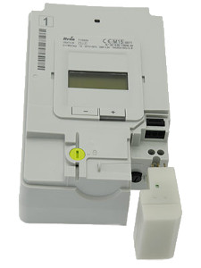
Linky
The Linky smart meter has a slot for a "LRT" module and a 3-pin header for teleinfo (the traditionals "I1" & "I2" as well as a power source named "A").
There are also two communication modes available: Historical (the only one available so far) & Standard (i.e. the new one starting with Linky).
LRT
The "Linky Radio Transmitter" (Emetteur Radio Linky) is a module developed to transmit the value to a household display. Specifications show they can be using either Zigbee or KNX. It was supposed to be totally open but I am yet to see a schematics of it.
At least the Interface Specification is available. I reused the name of Zigbee attributes for the MQTT publication.
Teleinfo
Official docs are available (in french) on Enedis's website, in particular NOI-CPT_02E for Teleinfo in general and NOI-CPT_54E for Linky in particular.
The electronics part is mainly based on work done a long time ago by others, specially Charles Hallard (Démystifier le décodage Téléinformation et l’optocoupleur SFH620 and PiTInfo V1.2, en finir avec la téléinfo capricieuse).
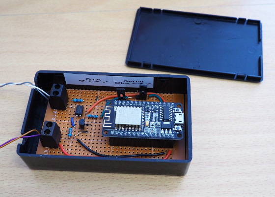
Board
My board is vague cousin of Charles Hallard's Wifinfo but where most of the components are already embedded on the nodemcu module.
CH340G (USB to UART)
Something worth noting is that CH340G seems to be struggling with 7N1 (7 bits instead of the usual 8). Although it doesn't matter for day to day usage of the ESP8266, it makes tests (emulation of the Teleinfo frames) more difficult.
It could be the driver though I am using Linux. Using boards (Amica) based on CP2102 or FT232 didn't show any problem.
Power
From the meter
In theory, the pins "A" and "I1" are maint to be used as the power source. That said, the characteristics are 6 Vrms (50 kHz) and 130mW. This is far from the ESP8266 requirements (~ 150mA) and if it would be easy to rectify and smooth the current, a storage system (super cap or battery) would be needed to deliver peaks of currents every time the data is published (re-charging being one while module is in deepsleep).
External 5V source
To keep things simple and since I already had a 5V source at my disposal, I used the embeded regulator on the nodemcu board (through the Vcc pin but it could have been through the micro-USB socket).
OTA
Having the circuit permanently plugged to the meter means that the option of remote updates is a big bonus. The module is off/asleep most of the time so the best method was the HTTP Server one. But in order to make things easier and more secure, there is a physical jumper to allow OTA or not. When jumper is on open position, no OTA is possible. In the other position (closed), every time the program starts (i.e. every minute), it checks if an upgrade is available.
This is were the additional python script comes handy. By running a webserver and comparing the MD5 checksum of the firmware on the module to the one on the server, it is possible to launch the upgrade sequence only when necessary.
MQTT
Selected data is transferred using the MQTT protocol. As mentioned above, the names/topics used are based of the ones in the ERL/LRT documentation.
ADCO  --> Serial Number used in topics (ssssssssssss)

BASE  ---->  cm/teleinfo-ssssssssssss/data/index {"value": "000073370"}
PAPP  ---->  cm/teleinfo-ssssssssssss/data/apparent_power {"value": "00320"}
IINST ---->  cm/teleinfo-ssssssssssss/data/rms_current {"value": "001"}
Since the tariff is a constant one and not a differential one, there is only one reading to report and there is no need to advertise which tariff is active. People dealing with Heures Pleines / Heures Creuses would have to change the code.
Deep sleep
In order to reduce the amount of power drained, reduce the heat production and because there was no need to keep the module on for nothing, I decided to turn the wifi off. But it turned out that it isn't as straightforward as it initially sounded. Just calling the corresponding fonctions doesn't really make any difference in term of power consumption and forums are full of examples looking really like black art.
On second thought, I decided to go to the deep sleep route which turned out to be easier to implement and perfectly adapted to this kind of usage. The teleinfo is continuous with values coming all the time but having a refresh every second or so has very limited interest. Even everything minute is kind of luxury.
The only downsides of deep sleep are the need of a physical wiring for reset purpose and that the programme really resets every time. In this case where the bridging is stateless (state/info is held by the smart meter and given every single time) it doesn't matter the least.
Next version
This version has been running for a while without any issue. Once the meter is properly registered by the supplier (they seem to have technical issues actually), they should be able to change the mode to "Standard".
This new mode is only in Linkys, uses a different serial speed (9600N7 instead of 1200N7) and provides more information. The "codes" are slightly different too.
There is no physical modification needed and everything is documented so making the software changes should not be too complicated.
Will see....
Code
As usual the code and schematics are available (AS IS) on github.